To find the position and the related measurements of all numbered blocks,
see the
CHEOPS SHAFTS
drawing
at the CYBER DRAWINGS
page.
All
copyrights Rudolf Gantenbrink 1999
After an initial horizontal section of 1.96 meters (penetrating the first block of the Queen's Chamber wall), the shaft inclines at an average angle of 39.6078°, which we determined by taking 24 measurements over a distance of 28 meters.
Between Block No. 2 and No. 3 we discovered settling of 3 to 4 centimeters, almost certainly resulting from the pressure exerted by the roof beams of the Queen's Chamber. The lower northern shaft displays similar settling, though there it is distributed along the course of three blocks.
The first three joints of the shaft are vertical, to deflect the pressure of the roof beams into the horizontal plane.
Block No. 8 has an unusually irregular surface. This riddle is solved by Block No. 9, one wall and the ceiling of which are rough. But the western wall is relatively smooth and shows signs of having been worked with a chipping chisel. Apparently the ancient Egyptian builders first initially shaped the shaft blocks with a pointed chisel, which explains the uneven surface, and then dressed them with a chipping chisel. Blocks No. 8 and 9 were evidently built into the structure in unfinished form. In 1992 we also found three unfinished blocks in the upper shafts.
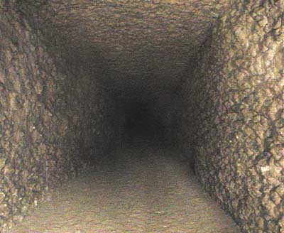
The unusually rough surface of Block No. 8.
Blocks No. 16 and 17 are offset by about 3 to 4 centimeters. It is impossible to determine with any certainty whether this deviation occurred during original construction or at a later date. This spot lies just under the floor level of the King's Chamber, where Petrie discovered unusual settling. (PETRIE, W.M.F., "Ten Years Digging in Egypt", New York, s.d.) It is possible that this settling, and the observed deviations were caused by an earthquake during the pyramid's construction.
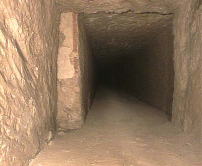
Because of the shift we can see an original red marking line
of the builders.
From Block No. 19 onwards, we detected strange scratches on the walls of the shaft, extending all the way up to Block No. 26. Depending on the surface texture of the walls, these scratches appear with varying clarity, at a consistent height of 2 to 3 centimeters above the shaft floor. The scratches are not very deep and are visible only because they penetrate the stones' patina. Since the scratches extend over the block joints, it is obvious that they were made after this shaft sequence was finished. It would appear that something was dragged up through the shaft subsequent to its completion.
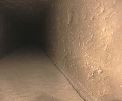
One example of the scratches at the lower part of the west wall.
Shortly after the joint leading to Block No. 21, a bit of light-colored mortar (most likely gypsum) adhering to the west wall of the shaft gives the impression that here, something was originally attached to the wall.

The streak of mortar at the right showing a tiny canal
at its lower part.
Please note also the scratches just above the floor
on both of the walls.
In 1843 Borchardt found a similar impression, somewhat larger, on the walls of the Great Gallery (BORCHARDT, L., "Einiges zur dritten Bauperiode," Berlin 1930). He established that it was made of mortar, in which a long, round object had originally been embedded, and later removed. He could not determine what that object may have been, but he assumed that it had been attached to the Gallery wall by means of the mortar.
We made an identical find farther along the shaft, at Block No. 26. Just as with Block No. 21, the impression here is located on the west wall of the shaft, at the beginning of the block.
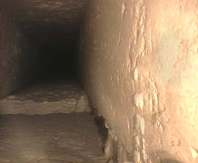
This similar feature located just before the step in the floor
also shows a kind of straight, hollow impression.
There may be a connection between these hollow impressions and the scratches. It is quite possible that the mortar was used to temporarily fasten strings to the shaft wall. These strings could have been removed later by giving them a sharp tug, causing the mortar to break away and leaving behind the kind of hollow impression of the strings that we observe today.
At the beginning of Block No. 26 , a large section of the floor has broken away. This is the worst damage we observed anywhere in the shaft sequences so far investigated. At this point, however, the pressure on the shaft amounts to only one-third of the maximum value. Near the Queen's Chamber, 115 meters of pyramid material press downward on the shaft. But only 35 meters of material press down on this spot, where we observe the greatest shaft damage. This highly unusual finding can have resulted only from one of two possible causes:
1. Extremely inept construction work below Block No. 25 and 26. It must be remembered, however, that it is this final section of the shaft which otherwise displays the highest quality workmanship observed anywhere in the shafts system.
2. The existence of an as yet undiscovered structure below or above this shaft section. Such a structure could produce a pressure peak, which could in turn focus considerable additional force on the shaft and possibly cause the observed damage.

The broken floor exposes a large step which in reality is simply the
abutting face of the next block.
For Upuaut-2 this was almost like running into a tank trap.
At block No. 26, the shaft floor is marked by a long cutting groove. We found more such grooves in the floors of Blocks No. 27 and 28
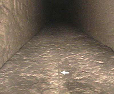
One of the cutting grooves runs parallel to the shaft
and continues a long way up.
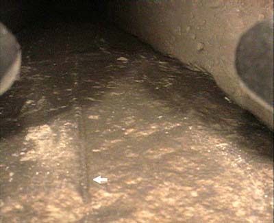
Another cutting groove in close-up shows a rounded end profile.
This is typical of cutting grooves.
(The two oval structures on the left and right are Upuaut's
front-bumpers.)
Such grooves were caused during construction of precise joints. Two blocks, which had been preliminarily worked with a chipping chisel, were shoved together. Then a saw was run down through the gap remaining between the two blocks, removing material from the ends of both. This procedure created a precise joint between two adjoining blocks.

Cutting of precise joints using a copper bladed saw.
This method also leaves behind a cutting groove on the block underneath, a fact which testifies to the use of this method.

Photo Dr. Richard Schreiber
The cutting groove on the surface beneath a joint of casing stones.
(Southern Queen's Pyramid GIc Giza / right block missing.)
Once the cutting was finished, the blocks where again shoved together
to close the gap left by the saw.
For this reason the upper block covers the cutting groove. This detail
even shows us the direction from which the blocks were added.
Based on the grooves found in the shaft, we can assume that, before their insertion as floor slabs, these blocks served as a base for the cutting of precision joints.
This gives rise to a crucial question: exactly which precision joints were cut here?
The shaft blocks themselves were only dressed with the chisel. We observed ample evidence of this in the Caviglia Tunnel, on the lower sides of the shaft blocks, as well as at several sites of block displacement, which exposed the abutting edges. At the upper southern shaft outlet, both outer sides of the blocks are visible. These, too, were worked only with the chisel. Thus, as 9 of a total of 10 surfaces of a shaft block were definitely chiseled, we can well assume that the shafts were constructed without recourse to sawing.
The pyramid's nearest casing stones, which lie 19 meters distant from this spot in the shaft, were cut in their final position. We know this because the stones located directly beneath the casing stones display cutting grooves.
The pyramid's corridor and chamber system, which also displays precise, cut joints, had been completed long before this shaft construction level was reached.
Taken together, these findings constitute a compelling case for a possible, as yet undiscovered structure - for which precision joints where made - in this upper region of the southern, Queen's Chamber shaft.
Block No. 27 is partially polished.
Block No. 28 is extremely well-crafted, smoothly polished and consists of a lighter-colored material than that of the other blocks. In some spots, including the ceiling just before the mysterious closure stone, very fine, dark-gray veins are visible in the stone, evidence of the material's high degree of homogeneity. The veins cross one another, proving that they are not simply fissures. (It is physically impossible for static fissures in stone to run criss-cross. See the
third photo, below.)
At the end of Block No. 28, the shaft is closed by an unusual, smoothly polished stone.


The closure stone.
Protruding from two holes drilled in the stone are bent, slightly conical copper fittings. The openings of the drill holes contain a black, tarry mass. (See the close-up photos, below.) The left fitting is broken off about halfway up. The broken piece slid down the shaft to the end of Block No. 27, where it still lies.
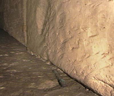
The broken bit of copper fitting.
Both fittings display round, white impressions, which have discolored both the stone and the fittings themselves. (See the two close-up photos, below.) The impressions were evidently left by a gypsum-like material, which has since broken off.


Close-up of the fittings.

Close-up of the left fittings.
Between the closure stone and the shaft floor is a gap of 5 to 7 millimeters, which we determined by comparison with the diameter of Upuaut-2's laser beam. Thus, the visible lower edge of the stone does not lie totally flush with the floor. Close examination of the broken, lower right corner shows that it is held in place by a groove or recess, and that, at this point, the stone is only about 5 millimeters wider than the shaft itself.

The recess in the wall is visible at the broken edge of the closure
stone. (The oval structure at the right is Upuaut's front-bumper.)
The surfaces of the shaft blocks which lie on the floor have chamfered edges. Thus, in the video wide shots, the lower left corner of the stone is also visible (see wide shot,
above). Here, too, the stone is only slightly wider than the shaft. The lack of shadow at the upper edge of the stone indicates that it is taller than the shaft itself, but there is no way of establishing how far the stone extends into the ceiling.
No traces of mortar are visible on the closurestone. This is unusual, as the joints of most shaft blocks do show such traces. We were able to recover bits of white gypsum mortar from the shaft, indicating that the shaft was indeed laid using mortar. But the closure stone was apparently mounted with great precision and held in place by grooves or recesses, without using mortar. Thus, we may well assume that the stone is, in some way or another, moveable.
In May 1993, hoping to supplement our purely visual evaluation of the copper fittings, I asked English Metallurgist Hugh Tyrer to examine the relevant video material. (Tyrer and his company HT Consultants played a key role in metallurgical aspects of the development of the Concorde aircraft.)
On the basis of the two-dimensional video images, Tyrer was able to come to several conclusions:
1. The corrosion coloring and the surface texture indicate that the fittings are indeed made of copper or bronze.
2. The extent of the corrosion is quite normal for a period of 4000 years, given the prevailing level of humidity within the pyramid.
3. The broken piece of the left fitting and the left fitting itself both display smooth fracture surfaces. Thus, the piece of fitting did not break off due to outright corrosion. The smooth fracture surfaces would indicate that the fittings were made of cold-forged material. During the forging process the material was stretched, causing a very fine crack. The ongoing process of corrosion eventually caused the fitting to break at that fine crack.
4. Traces of hammering carried out are visible on the left fitting, at the point at which it emerges from the stone. This is an indication that the fitting was first pushed through the hole drilled in the stone, and then struck with a hammer, to bend it downward at a 90° angle.
THE UPPER NORTHERN SHAFT
THE LOWER NORTHERN SHAFT THE UPPER SOUTHERN SHAFT
|

